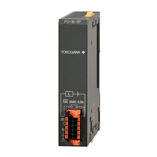


The power supply module supplies power to each modules.
Module specifications
| Item | Specification |
|---|---|
| Model | A8HPU-16-0P |
| Power supply voltage | 24V DC |
| Power supply voltage Variation range(*1) | 20.4~28.8V DC (-15% to +20%) |
| Rated input power | 45W |
| Inrush current | 10Amax. (28.8V DC、Ta=25℃) |
| Rated output power | 40W |
| Rated output voltage | 5.2V DC |
| Rated output current | 7.7A |
| Protection circuit(*2) | Built-in time-lag fuse (non-replaceable) Reverse polarity protection circuit |
| Insulation resistance | 5 MΩ or more at 500 VDC (between all FG terminals and the other terminals and circuit (*2)) 5 MΩ or more at 500 VDC (between all FAIL signal contact output terminals and the other terminals and circuit (*3)) |
| Withstand voltage | 500 VAC for 1 minute (between all FG terminals and the other terminals (*2)) 1000 VAC for 1 minute (between all FAIL signal contact outputs terminals and the other terminals (*3)) |
| Hold-up time | 5ms (24V) 2ms (20.4V) |
| FAIL signal contact output(*4) | Contact rating: 24 VDC (20.4 to 28.8 VDC) Rated current: 0.25 A (0.3 A max.) ON voltage: 0.5 V Leakage current when off: 0.1 mA |
| External connection(*5) | 10-pole push-in terminal block |
| Dimensions | 23(W)×100(H)×84.6(D)mm(excluding protrusions) |
| Weight | 145g |
*1: Avoid connecting a power supply that produces over 30 VDC. Avoid connecting an AC power supply. Connecting one of these power supplies may cause a malfunction.
*2: The FAIL signal contact output terminal, 24VDC terminal, and internal circuit.
*3: The FG terminal, 24VDC terminal, and internal circuit.
*4: If an inductive load, such as a relay, is connected, a surge suppressor is required on the load side. Install a surge suppressor or diode near the load to ensure that the voltage applied to the FAIL signal contact output terminal does not exceed the contact rating.
*5: When wiring to this module, be sure to use the terminal block provided. A 10-pole push-in terminal block (model: A2320JT) is available as spare parts.